Dev Update: Solving Thermodynamics
Nothing in life is certain except death, taxes, and laws of thermodynamics
Greetings, fellow rocket scientists!
One of the big features which I get asked about all the time is the re-entry effect. I’ve been putting this feature off for the future for a long time because I didn’t know how to even get started with it. You need not only to add the whole thermodynamics simulation into the game while trying to maintain the game’s performance, but also somehow solve a re-entry effect for the crafts of any shape and form. Not many other games have done this before and there is very little info out there on how to properly do it.
But now I think I have gathered enough expertise to accept this challenge. Because the whole new system not only should improve the depth of the game and bring a lot of new rocket parts, but it will solve one of the big problems it has. See, the game is capable of maintaining several physics simulations in the background. So if you launch a plane and then return to the space center, it will continue the flight (if it is stable enough). In the meantime you can launch another rocket or assemble a spacecraft and then return to your plane in an hour and continue the flight.
The drawback of this feature is that it will simulate any other craft in the background even if it is just a used decoupled stage that entered the atmosphere. But any background physics simulation locks timewarp to a maximum of 10x which can be annoying. But if we add the aerodynamic heating of atmosphere entry vehicles into the mix, almost all debris should quickly burn and there will be no problem with that.
So there were basically two parts of research I had to make: thermodynamics itself and the re-entry and part heat visuals. Let’s talk about thermodynamics first.
After reading different articles on the subject for several days straight and nearly going crazy from the amount of math that dropped into my head, I decided to stop and approach this task incrementally as I did with aerodynamics. It is much better to start with a simpler, predictable and understandable system and refine it, adding complexity over time, than just be buried under the formulas creep and don’t produce anything meaningful.
So, what are the sources of heat gains and losses that most spacecrafts will experience? There are a lot of them, but I decided to start with these ones:
- incoming solar radiance;
- outgoing thermal radiation;
- modules that produce thermal energy during the work (engines, command modules, instruments, charging batteries etc)
- parts that dissipate heat over time, like radiators;
- aerodynamic heating;
- atmospheric cooling or heating due to convection.
Most of the formulas for heat flux above are not very complicated (except for aerodynamic heating). But they are non-linear either, so you can’t just write it as a function of time, you need to integrate it. It would not be a problem for physics simulation, since we have plenty of integration in it already. But spacecraft will constantly receive solar radiation and radiate heat even during the math simulation. So it needs to support time warps up to one month per second and give consistent results.
While you can find an analytical solution for thermal radiation integration, it is not so easy for incoming solar radiance. Because it is a function of time and distance from the Sun and distance can not be described as a simple function of time, because it will depend on the spacecraft’s orbit. But I think I will find or invent some approximation for that.
As for aerodynamic heating it is much more complicated than everything I encountered before. There are dozens of papers published by NASA with complicated math I can barely wrap my head around. And even if I could understand all of this, it would be very computationally expensive to add into the game.
 My brain immediately turns off when I see something like this
But I found an approximation that I could use to begin with.
\[\begin{equation} q_{s} = k\left ( \frac{p}{R_{n}} \right )^{0.5}V^{3} \label{eq:aerodynamics_heating_flux} \end{equation}\]Nice and simple formula, but the problem is that k is the precalculated constant for a specific atmosphere and I found values for it only for Earth and Mars. Also R is the bluntness of the rocket part. I understand what this means and why it is there but I didn’t find out yet how this value is calculated or at least in what ranges it lies. If you know any of this or at least could point me in the right direction please let me know in the comments below.
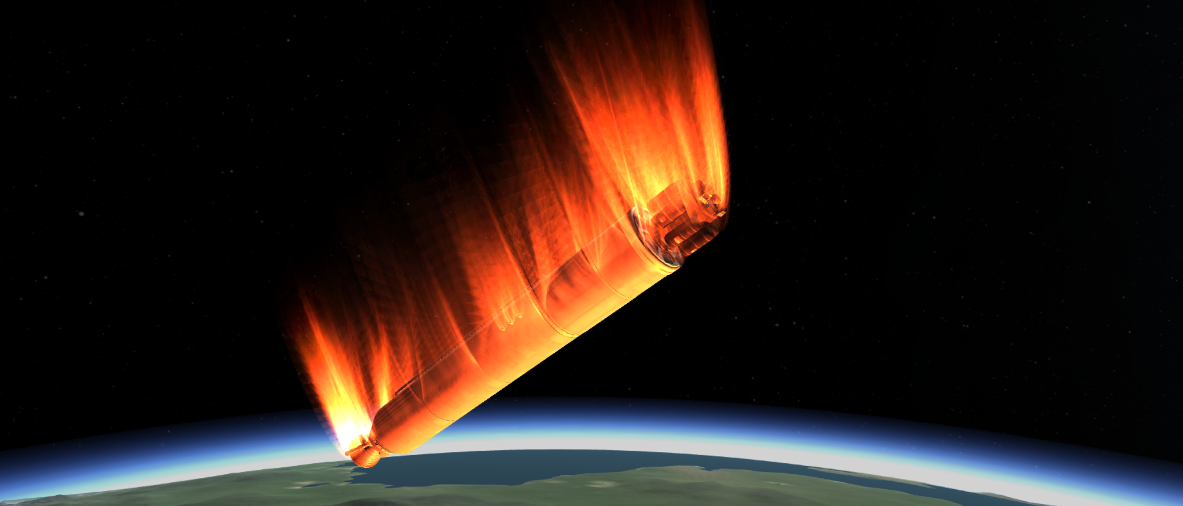
Enough of math for today. Let’s talk about the visual component of reentry heating. It is a combination of plasma and flames which should encompass the spacecraft when it enters the atmosphere at a high speed.

It would be easy to do if you know the shape of the rocket ahead of time. But in this game spacecraft could be of any shape. And not many games have rocket construction combined with the re-entry heating, so this problem has no commonly known solution.
There is a talk on Youtube “Unite 2013 - Building a new universe in Kerbal Space Program” where the original developers of the game talk about their solution of this problem. They basically take the rocket part mesh and render it multiple times with some offset and increasing opacity and scale.
 It is interesting, that this shader is also used for fur rendering
The drawback of this solution is that you can notice bands of color along this effect. You can decrease these visual artifacts by increasing the number of render steps or by applying some dithering algorithm on top of that. But this solution is expensive and pretty limited in visual expression. I didn’t find anything else on the topic, so I decided to try to implement re-entry effect by myself.
I took a simple quad sphere, copied it, scaled it a bit and started experimenting. After several days of tinkering with shader magic I ended up with something usable.
 All screenshots will be from Unity Editor, since I didn’t incorporate this effect into the game yet
But how can we apply this effect on any rocket part? See, the great property of the quad sphere is that it has uniformly distributed vertices.
 A simple quad sphere wireframe. In fact this is the basis also for planet generation
So we can apply vertex offsets to it from any direction. And we need this mesh property, because spacecraft can be in any orientation when entering the atmosphere. This means we can’t take rocket part mesh, scale it and just apply this shader. Because most of the parts have meshes with sparsely distributed vertices.
 Here is an example of a Fuel Tank mesh, there are not a lot of vertices, especially at the bottom
 Another example: this is a command module mesh, it is better suited for this effect, but vertices still non-unifromly distributed and effect will look bad in some cases
So we need a mesh that will follow the shape of the part but would have a uniform vertex distribution. Manually creating such a mesh just for re-entry effect for each existing rocket part in the game and for all future ones is not an option. I heard you can easily do it using Houdini, but I have no time to learn a new tool and also I can’t afford it. I am pretty sure you can do it in Blender, but the workflow would not be ideal. So is there any way to do it faster, preferably using only Unity Editor?
After some hard thinking I remembered my signed distance field terrain generation experiments from three years ago.
 Every experiment is a great for gaining an experience and expertise even if it had no use in the beginning
Here is a terrain generated using a signed distance field or shortly SDF. SDF is a scalar field for each given point of which we can obtain a distance from some surface. If the distance is negative then this point lies inside this surface, if positive then outside. Then we can build a model from any SDF using a mesh extraction algorithm such as Marching Cubes. Mesh, generated in this way, has a property that we seek – a pretty uniform vertex distribution per unit of volume. On the screenshot above the SDF was generated by the noise function. But the great news is that we can turn any model into SDF first and then reconstruct it using the mentioned algorithm!
Unity has a built-in mesh to SDF generator. But has no tools for the other way around. So I’ve implemented the Marching Cubes algorithm specifically for my case. And tried to reconstruct the command module from above using it.
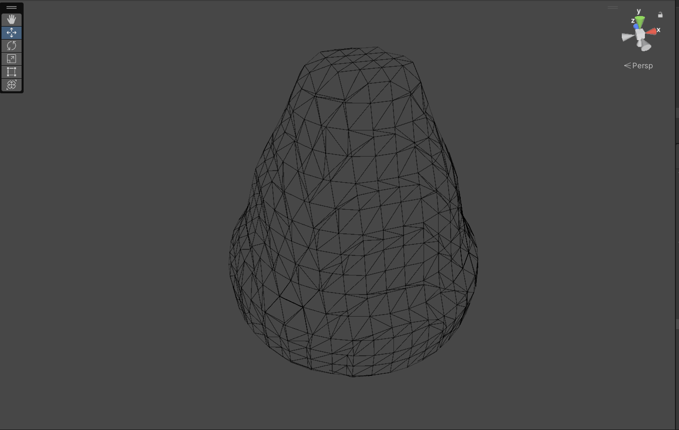
The result was closer to what I need, but as you can see, there are a lot of unnecessary vertices in some places which not only affect the quality of the effect, but would also be a bit taxing.
After some additional time spent on research I found and implemented another algorithm called Surface Nets. It generates less accurate representation of the surface, but produces less vertices and they are more uniform.
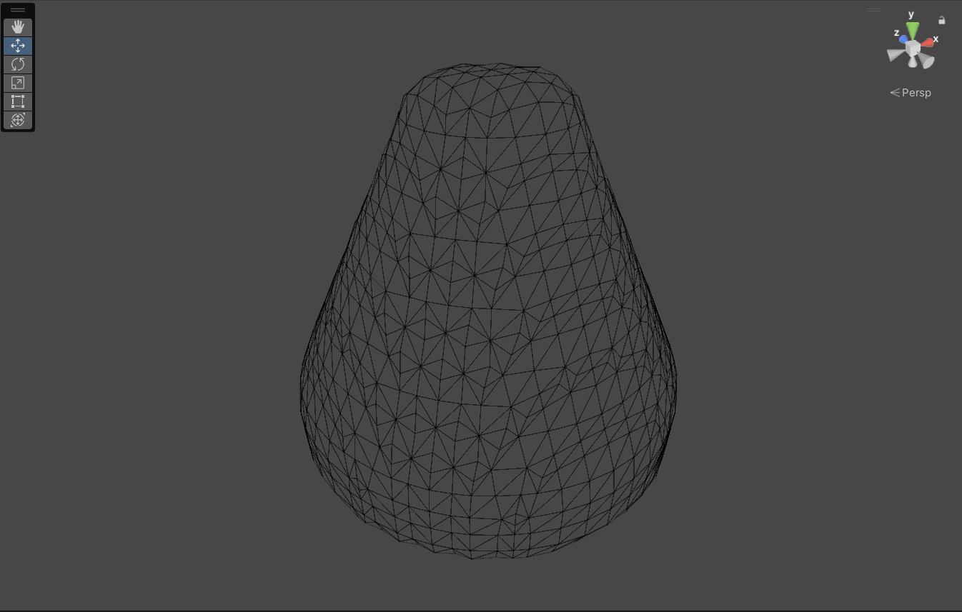
This was exactly what I needed. I plugged the resulting mesh into my earlier shader and got the following results.
 There are a lot that can be improved here but I think it is a good starting point
 Thanks to uniform mesh, the effect works from any side
So I’ve written a special tool for Unity, that can convert meshes with a single button press.

While the process is greatly automated now, it still requires a bunch of manual tweaking for each rocket part. I think this is as far as I can push automation forward. And I believe I have a good foundation now on which thermodynamics effects will be built upon. But there are still a lot of work with the shader. I need to account parts occlusion, rocket bounds, add flutter and pulse, also make it more dynamic and varied.
 Here is a quick proof of concept, that it will work for assembled rocket
This dev update is already huge and I told only 20% of all things I needed to research and experiment with while working on thermodynamics for the game. I will probably continue this story another time (or better record a video about it at some point). But I need to get back to v0.22.0 development which has a big scope and not a lot of time to work with.
Thank you for reading this post and have a nice flight!